TOTALLY ENCLOSED HOOD & AIR SYSTEM
The closed PM hoods, encasing entire paper machines are designed to satisfy the demand of high dew point operation,
thereby achieving an efficient, uniform and economical paper web drying.
 During the drying process a large quantity of moisture is evaporated from the paper web. This moisture is discharged to
the atmosphere through Hood exhaust fans. Part of the heat carried along with the exhaust air is recovered in pre-heating
the Hood Make-up air in Heat Recovery Units.
During the drying process a large quantity of moisture is evaporated from the paper web. This moisture is discharged to
the atmosphere through Hood exhaust fans. Part of the heat carried along with the exhaust air is recovered in pre-heating
the Hood Make-up air in Heat Recovery Units.
The make-up air, thus pre-heated, is further heated in water-air and steam -air heat exchangers and introduced in the
paper machine through various blow boxes via centrifugal supply air fan and ducting.
APPROX HEAT CONSUMPTION IN A MULTICYLINDER MACHINE WITH HEAT RECOVERY
| | |
Open
Hood |
Closed
Hood |
Closed
Hood |
| Exhaust Air Dew Point |
ºC |
40 |
53 |
58 |
| Absolute Humidity in exhaust air |
Kg/Kg |
0.05 |
0.1 |
0.14 |
| Dry bulb temp. of exhaust air |
ºC |
55 |
75 |
82 |
| Supply air temperature in M/c room |
ºC |
25 |
25 |
25 |
| Absolute Humidity in supply air |
Kg/Kg |
0.01 |
0.01 |
0.01 |
| Supply air Temperature after Heat Recovery
|
ºC |
35 |
55 |
60 |
| Proportion of heated supply air/ exhaust air
|
|
0.3 |
0.7 |
0.85 |
| Approx.heat consumption |
Kg/Kg H2O |
3400 |
3125 |
3000 |
The Totally Enclosed Hood comprise of the following main units :
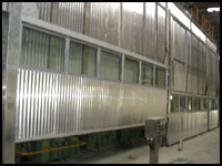
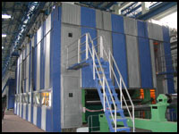
CLOSED HOOD
The Closed Hood, of fully insulated design, encloses the dryer section of the Paper-Machine. The construction of the
Hood is suitable for 55°C to 62° C dew point to optimize air system thermal requirements.
 Hood Framework
The hood is built up with a framework of Hot Dip Galvanized mild steel profiles.
Roof Panels
The roof panels are made of with resin bonded mineral wool insulation of 100 mm thickness sandwiched between
1.0 mm thick and 1 mm thick plain aluminium sheets on inside and outside respectively.
Wall Panels
The wall panels are made of 100 mm thick mineral wool insulation sandwiched between plain aluminium sheet of
1.0 mm thickness on the inside and corrugated aluminium sheet of 0.81 mm thickness on the outside.
Exhaust Plenum
The exhaust plenum is made of aluminium sheet below the roof at the drive side along the entire length of the hood.
The exhaust duct is equipped with exhaust openings and sliding dampers towards the machine between every second
pair of roof beams on the drive side. Cross ducts sucking air from the front side of the hood are also arranged between
every other second pair of roof beams. Thus the exhaust air from the hood is sucked from an equal number of suction
opening on the front and on the back side of the roof.
Lifting Doors
The lower part of the tender side along its entire length is equipped with specially designed lifting doors of 1mm thick
Aluminium sheets with 50 mm thk mineral wool insulation. These doors are fitted with inspection windows along the
full length of the hood. The lifting device for the tender side lifting doors consist of reduction gear unit with brake motor.
These are equipped with limit switches (up/down safety switches to prevent the door from going higher than the upper
limit switch), wires, guide wheels, wire drum and sealing between doors and hood. The height of lifting doors is ~2100
mm.
Sliding Doors
The lower part of the rear side of each dryer group is equipped with a sliding door having 50 mm thick mineral wool insulation covered with 1mm thick plain Aluminium sheet. Swing doors are also provided at appropriate locations. These are of Aluminium construction with mineral wool insulation and inspection windows.
Walkways & handrails
A full length walkway is provided on top of the Hood at the tender side and the gable sides complete with handrails.
MAKE UP AIR SYSTEM
The hood makeup air is preheated by means exhaust air at Heat Recovery Unit and then by means of condensate water, flash steam and live steam up to a temperature of 110°c and delivered through a centrifugal supply air fan to the pocket ventilation and other blow boxes.
Each system comprises of :
- Steam coils constructed of Hot Dip Galvanized steel tubes fitted with steel fins all mounted in a welded steel frame. Hot water & Flash steam is utilized in the 1st & 2nd bank of heaters and Live steam is introduced in the balance 3 banks of heaters to minimize consumption of live steam.
- Inlet vane control damper of MS construction suitable for manual /actuator operation.
Centrifugal supply air fan with MS casing and impeller painted with Heat Resistance Paint. Each fan will be complete with V belt drive, belt protection guard and flexible connection at fan inlet and outlet.
- The hot air is supplied to the various blow boxes by a complete ducting network.
HEAT RECOVERY AND WET AIR EXHAUST
The hood exhaust system is designed to ensure even & controlled removal of humid process vapours from the hood. The wet air leaving the paper machine is used for Heat Recovery before it is exhausted into the atmosphere. The recovered heat is utilized for preheating the make up air and contribute to the high overall thermal efficiency of the system.
The moist air from the totally enclosed hood is exhausted by a system comprising :
- Connection piece made of Aluminium between the Hood and Heat Recovery Unit.
- Cross flow heat exchanger consisting of rectangular aluminium plates / aluminium tubes so arranged that air passages are
formed between them. The hood exhaust air flows through the alternate passages whereas the ambient air flows through the intervening passages. The direction of flow in the adjacent passages is at right angles to each other (cross flow). This air is
then further heated in the heat exchangers in three stages using hot condensate water, flash steam and live steam before
being delivered by means of a centrifugal supply air fan to the blow boxes.
- Inlet vane control damper in steel construction suitable for manual / actuator operation before the exhaust air fans.
- Axial flow exhaust air fans with impeller made of cast aluminium alloy and casing made of mild steel, hot dipped galvanized.
- Exhaust air ductings made of Aluminium crimped on MS flanges.
BASEMENT ENCLOSURE
The basement of the Hood is totally enclosed by an enclosure of un-insulated design for uniform drying and to prevent cooling
of drying cylinders by infiltrated cold air entering the Hood from bottom side of the cylinders.
The basement enclosure comprises of:
- Un-Insulated aluminium wall panels.
- Un-Insulated aluminium sliding doors.
- Un-Insulated aluminium hinged doors.
INSTRUMENTS & CONTROLS (Logic of Lifting Door Operations and other Controls)
Lifting Door Operation
The lifting device for the tender side lifting doors consists of reduction gear unit with brake motor. These are equipped with limit switches (up/down safety switches to prevent the door from going higher than the upper limit switch.
2 Nos. Photo Electric Cells are provided at suitable location at paper entry and exit point to detect any paper breakage immediately and will raise the lifting doors automatically.
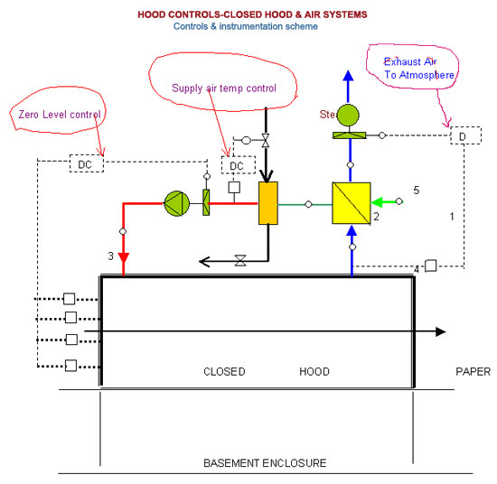
HOOD CONTROLS
Supply air temperature
Temperature of supply air is to be controlled by controlling quantity of steam to the steam air heater with a steam control valve.
A thermostat provided upstream of the Air-Heaters senses the variations in temperature from a predetermined Set Point and
actuates the opening / closing of the Steam Control Valve to maintain the desired hot air temperature.
Exhaust air dew point
For controlling the dew point temperature of exhaust air, temperature sensing device (RTD) is provided in the exhaust air duct and exhaust fan damper is to be adjusted by an electrically operated modulating actuator through your PLC to maintain a pre determined set point of the exhaust air.
ZERO-pressure level
For controlling the ZERO -pressure level in the Hood, a set of pressure sensing device is provided at the backside panels of the Hood and supply air fan damper is adjusted by an electrically operated modulating actuator through your PLC to maintain a predetermined set point of the average pressure level.
Control Principle
- First exhaust air amount is adjusted so that the air humidity is as required.
- Then supply air amount is adjusted so that hood -level is as required (~2 meters above floor level).
|